Title: Electrical Schematics
Description: The electrical schematic is the street rod technician’s key to designing and solving many of the electrical problems in circuits. A schematic can be thought of as a road map used to follow the current through the circuit. The schematic shows the symbols and points used to indicate a junction, splice, a male or female connector, components, fuses, and any other part of the circuit. It tells the street rod technician how current gets from one point to another, through switches, fuses, loads, and so on.
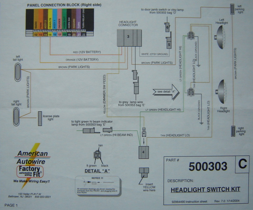
Remember that a schematic is not drawn to scale. For example, both a 6-foot and 4-foot length of wire in the vehicle may be represented by a 2-inch line on the schematic. Also, the actual location and physical appearance of the components are not always the same as in the vehicle. The illustration to above shows an example of a headlight switch kit schematic from American Autowire.
Relationship to Street Rods: Schematics are used by many street rod technician's to design, build and troubleshoot the electrical circuit correctly. The above schematic shows several parallel circuits. First, note that the wire (labeled as red 12 Volts Battery) coming from the “headlts” connector (# 15) goes into a headlight connector. From there the circuit goes to the left and right tail lights. Another circuit comes out of the headlight connector and feeds electricity to the left and right parking lights. Another circuit comes from the headlight connector to the courtesy lamp. Finally, another circuit feeds electricity to the left and right headlights. Although each manufacturer may use different approaches to drawing a schematic, remember that the purpose of having a schematic is to help the street rod technician design, build, and troubleshoot electrical circuits correctly.
Back to Electrical Principles