Title: Four Stroke Timing Diagram
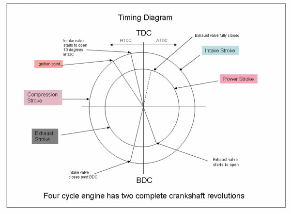
Describing the Principle: A timing diagram is a method used to identify the time at which all of the four stroke events occur on a typical four-stroke engine. A timing diagram is shown to the left. The diagram is set on a vertical and horizontal axis. There are 360 degrees around the axis.
One way to look at this diagram is to think of these events in terms of the position of the crankshaft and 360 degrees rotation. For example, at the top of the diagram, the piston would be located exactly at TDC (Top Dead Center). Any event that happens before TDC is referred to as BTDC or before top dead center. Any event that happens after top dead center is called ATDC or after top dead center. The mark at the bottom of the graph would illustrate the position of the piston at BDC. Two circles are shown to represent two complete revolutions of the crankshaft. During the four cycles of operation, the crankshaft revolves two complete revolutions or 720 degrees of rotation.
To begin, the intake valves open about 10 degrees BTDC. The intake stroke stops about 10 ABDC. The compression stroke then continues to the ignition point, about 15 degrees BTDC. The power stroke goes to about 12 degrees BBDC. The exhaust stroke continues to about 10 degrees BTDC at which time the cycle starts all over again. Although each point on the timing diagram is just an example, all four-stroke events generally occur somewhat near the points shown. Keep in mind that this timing diagram is only used to explain the principles of operation and the general timing of these events in relationship to the position of the crankshaft.

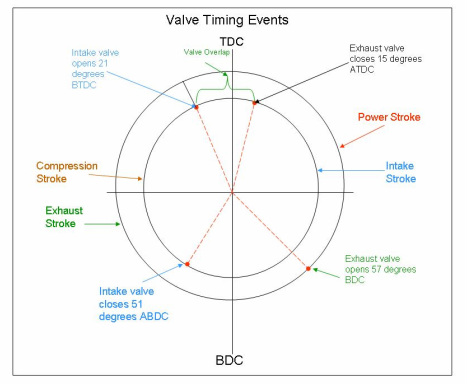
Although the first diagram showed how to read a four-stroke timing diagram, the drawing on the left shows a more accurate picture of the four-stroke valve timing events. For example, the intake stroke actually starts when the exhaust valve closes about 15 degrees ATDC. The intake valve remains open to about 51 degrees ABDC. The compression stroke then starts and compresses the air/fuel mixture up to TDC. The ignition varies but in this case, occurs about 21 degrees BTDC. The power stroke starts at TDC and continues to about 57 degrees before BDC. The exhaust valves start to open and the exhaust stroke ends about 21 degrees BDC, at which time the intake valve starts to open again. Notice the valve overlap between the intake and exhaust valve. Keep in mind that these valve timing events can only be changed by purchasing a new camshaft that has different shapes to the camshaft intake and exhaust lobes.
Back to Mechanical Principles
Back to Mechanical Principles
|
|
|
|