|
|
|
|

Title: Levers and Mechanical Advantage
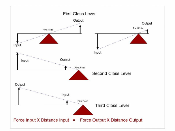
Describing the Principle: There are three types of levers that are used to increase an applied force or distance, or to get a mechanical advantage. Mechanical advantage is defined as the use of levers to gain either distance or force from the input to the output. These levers are called the first-class, second-class, and third-class levers shown in the drawing to the left.
Each lever has an input, an output, and a pivot point for a fulcrum. Depending on the type of lever, either force or distance can be gained. The difference among the three levers is the location of the pivot point, and the location of the input and output. These affect the input and output forces. Keep in mind that force times distance at the input must always equal force times distance at the output. For example, looking at the 1st class lever on the top left of the diagram, when a force is applied at the input on the left, then the lever is moved down a certain distance (indicated by the length of the arrow). This, in turn, will lift up the lever on the right side with a certain force and a certain distance. If the fulcrum is in the center, the input force times the distance would equal the output forces times the distances.
Now consider the fulcrum being moved to the right, as shown on the upper right diagram. In this case a smaller force, but a greater distance (input) would be needed to move the output a smaller distance, but with a greater force. The end result would be an increase in mechanical advantage, or in this case, increasing force. This would be similar to a crow bar action. Remember, if an increase in force is needed, then a greater distance must be applied. A good example of a 1st class lever is a rocker arm used to move valves open and closed. Rocker arms are designed on the principle of the 1st class lever, but with the fulcrum moved to the left. This design allows the output distance to increase so as to move the valve open further than what the camshaft lobe lift can do.
All machines today are designed based on the application of these three levers. Everything from wrenches, gears, steering linkages, brake pedal movement, pulleys. etc. base their design on the principles of these three levers.
Back to Mechanical Principles
|
|
|
|