Title: Series and Parallel Circuits
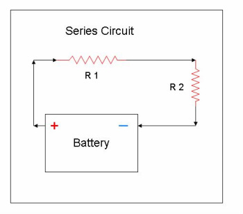
Description: There are several types of electrical circuits. The first one is called a series circuit. A series circuit consists of two or more resistors (loads) connected to a voltage source with only one path for the electricity to follow. An example is the circuit shown to the left. This circuit has two resistors placed in the path of the positive charges. The resistors are shown as R1 and R2. The jagged line is a symbol used to represent a resistor. Note that all of the amperage that comes out of the positive side of the battery must go through each resistor, then back to the negative side of the battery.
Description: There are several types of electrical circuits. The first one is called a series circuit. A series circuit consists of two or more resistors (loads) connected to a voltage source with only one path for the electricity to follow. An example is the circuit shown to the left. This circuit has two resistors placed in the path of the positive charges. The resistors are shown as R1 and R2. The jagged line is a symbol used to represent a resistor. Note that all of the amperage that comes out of the positive side of the battery must go through each resistor, then back to the negative side of the battery.

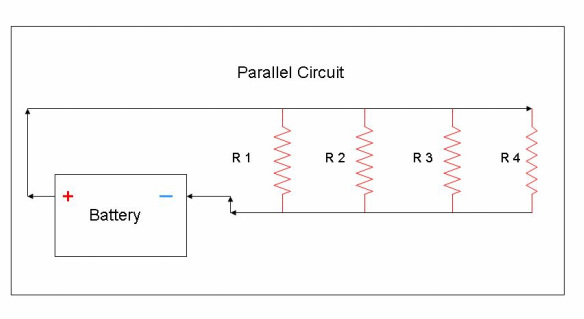
The second type of circuit is called a parallel circuit. Parallel circuits provide two or more paths for the current to flow through. Each path has separate loads or resistors and operates independently from the other parallel paths. In a parallel circuit, amperage can flow through more than one resistor or load at the same time. The illustration to the left shows a typical parallel circuit. Note that if one branch of the parallel circuit breaks or has an open circuit, the remaining resistors or loads still operate. This is the most common type of circuit used on street rods.
A third type of circuit is called a series-parallel circuit. This circuit is designed so that both series and parallel combinations exist within the same circuit. Although an important type of circuit, when working with street rods and electrical circuits, most often parallel circuits are encountered. However, within parallel circuits there may be times when there is additional series circuit loads.
A third type of circuit is called a series-parallel circuit. This circuit is designed so that both series and parallel combinations exist within the same circuit. Although an important type of circuit, when working with street rods and electrical circuits, most often parallel circuits are encountered. However, within parallel circuits there may be times when there is additional series circuit loads.

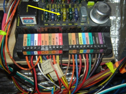
Relationship to Street Rods: Most circuits that are designed and built on a street rod are based on parallel circuitry. For example, the photo to the left shows a street rod main power panel or fuse panel made by American Autowire. There are fuses for each circuit shown by the yellow arrow. There are a total of 22 circuits that can be wired into this fuse panel. All of the bottom 22 connections are connected to the positive side of the battery through a fuse. However, several must go through the ignition switch as well. From these connections the wires go to the individual loads (radio, electric fuel pump, turn signals, dome lights, headlights, door locks, etc) as one of the parallel circuits. Also, after the load, each of the parallel circuits are grounded or connected to the negative side of the battery. If one circuit were shorted, or open, the rest of the circuits would still work. When designing and building electrical circuits for a street rod, think of the circuits as one big parallel circuit.
Back to Electrical Principles
Back to Electrical Principles